Command line interface and XML configuration
HELIOS++ can be run via a command line interface (CLI).
This has been the main interface for HELIOS++ before version 3.0 and is still available for users who prefer it over the Python API.
In this interface, all components of the simulation (scanners, platforms, scenes, surveys) are defined via configuration files in XML format.
In the HELIOS++ repo, you will find a data folder with a number of example surveys and scenes.
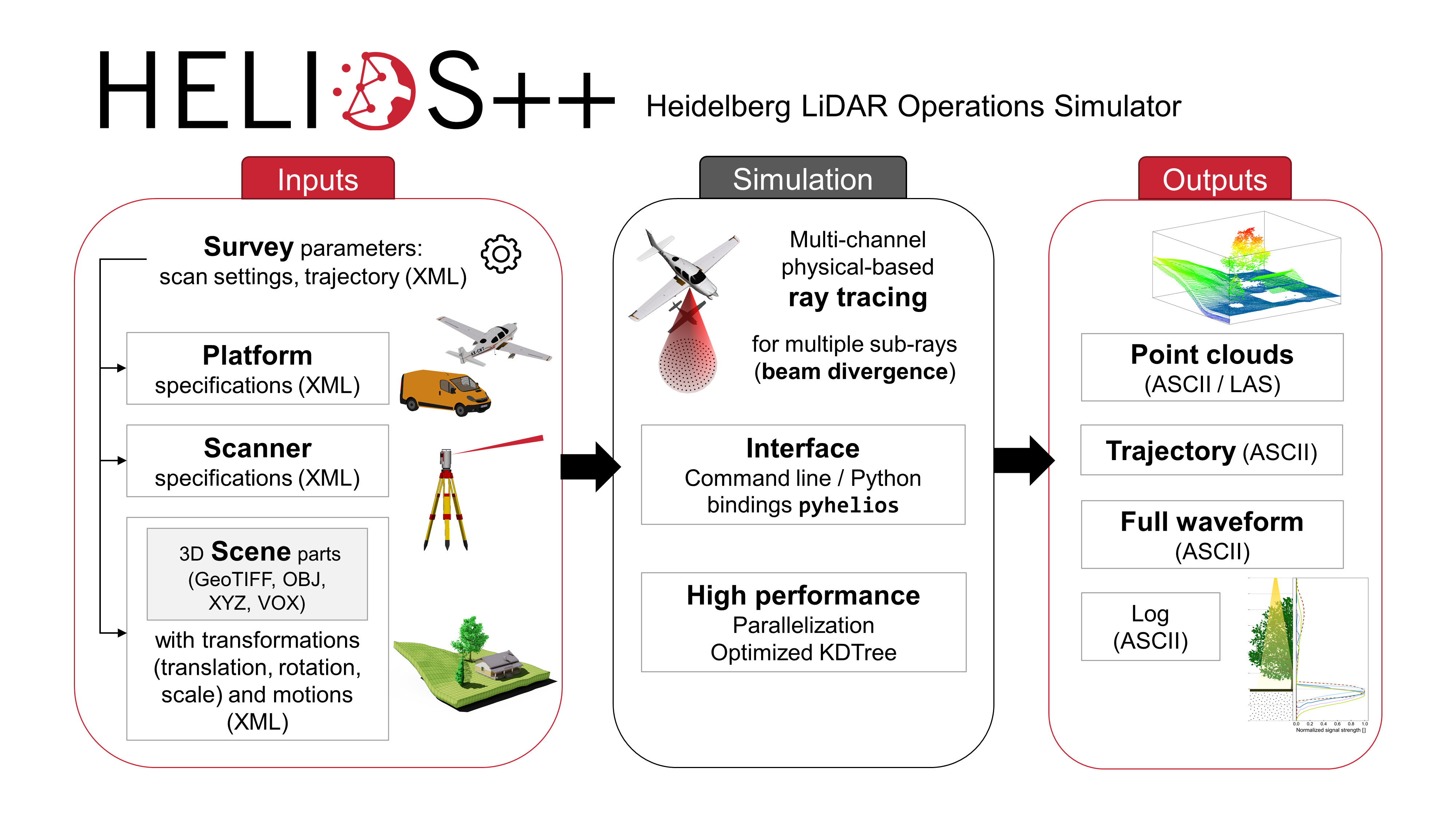
Typical workflow of a simulation with HELIOS++ (using XML files as input)
CLI usage
The CLI is available via the helios command, which is installed with the HELIOS++ Python package.
To print the HELIOS++ help message, type:
helios --help
This gives you an overview of additional, optional arguments.
To run a survey, use the following command:
helios <survey-file>
<survey-file> is the absolute or relative path to a survey XML file.
In this XML file, paths pointing to the scene XML, the platform XML and the scanner XML are provided.
If those paths are relative (recommended for sharing), their base directory needs to be in the list of HELIOS++ assetsPaths.
This way, it can be sufficient to only specify filepaths in the XML survey and scene files and then adding search folders to the assetPath list. To do so, add one or multiple file paths via the --assets argument, e.g.,
helios <survey-file> --assets <path/to/my/scenes> --assets <path/to/my/sceneparts>
If you have cloned the HELIOS++ repository, you can run the demos provided in the data folder. For example, to run the simple_survey.xml survey, use the following command:
helios data/surveys/demo/tls_arbaro_demo.xml
This will simulate terrestrial laser scanning (TLS) scans of two trees from two scan positions.
The output will be created in the output/arbaro_demo_tls-folder under the timestamp of the simulation start. This point cloud can be visualized e.g. using Cloud Compare.
To modify the format of the output (default: xyz), you can use the --format argument, e.g.,
helios data/surveys/demo/tls_arbaro_demo.xml --format laz
XML configuration
Survey XML
The survey XML file contains references to the components needed to build a simulation: The scene, the platform and the scanner. It also contains waypoint information needed to define the scan positions or trajectory.
Linking to the different components is done by specifying the absolute or relative path of the respective XML file in the <survey> tag, followed by a hashtag (#) and the ID of the entry:
<survey name="toyblocks_als"
    platform="data/platforms.xml#sr22"
    scanner="data/scanners_als.xml#riegl_vq-880g"
    scene="data/scenes/toyblocks/toyblocks_scene.xml#toyblocks_scene">
The platform attribute of the <survey> tag can also be set to “interpolated”.
In this case, the platform behavior will be defined by a function obtained through interpolation of given trajectory data, see Interpolated trajectories
Scanner settings and platform settings
Scanner settings and platform settings are defined at the document level before the <survey>-tag and/or within the <leg>-tags.
Setting one or more templates with defined scanner settings at the beginning of the file enables the reuse of these settings for the different legs.
Within the <scannerSettings> or <platformSettings> in each <leg>, the globally defined settings can be referenced by an ID using the template parameter.
Additionally, all settings can be given explicitly in the <scannerSettings> and platformSettings of the <leg>.
If the same setting is defined in a template and in a leg which uses the template, the value that is given in the leg is taken. So the priority is always: Leg -> Template -> Default
<?xml version="1.0"?>
<document>
        <platformSettings id="platform1" z="35.000" onGround="false" movePerSec_m="5" stopAndTurn="true"/>
        <scannerSettings id="scanner1" active="true" pulseFreq_hz="100000" scanAngle_deg="90" scanFreq_hz="50" trajectoryTimeInterval_s="0.05"/>
    <survey name="toyblocks_uls_stopturn" platform="data/platforms.xml#quadcopter" scanner="data/scanners_als.xml#riegl_vux-1uav" scene="data/scenes/toyblocks/toyblocks_scene.xml#toyblocks_scene">
    <!-- platform: quadcopter, deflector: rotating, stop and turn-mode
        OPTIONAL: detectorSettings and FWFSettings, examples below
            <detectorSettings accuracy_m="0.001" rangeMin_m="1.5" rangeMax_m="200"/>
            <FWFSettings winSize_ns="1.5" beamSampleQuality="3"/> -->
                <!-- leg000 -->
        <leg>
            <platformSettings template="platform1" x="-80.0" y="-50.0"/>
            <scannerSettings template="scanner1"/>
        </leg>
                <!-- leg001 -->
        <leg>
            <platformSettings template="platform1" x="80.0" y="-50.0"/>
            <scannerSettings template="scanner1"/>
        </leg>
                <!-- leg002 -->
        <leg>
            <platformSettings template="platform1" x="-80.0" y="50.0"/>
            <scannerSettings template="scanner1" pulseFreq_hz="300000"/>
        </leg>
                <!-- leg003 -->
        <leg>
            <platformSettings template="platform1" x="80.0" y="50.0"/>
            <scannerSettings template="scanner1" active="false"/>
        </leg>
    </survey>
</document>
In this example, the platformSettings template “platform1” is used for all flight lines (legs), so only the x and y position have to be specified for each leg.
Furthermore, all legs use the template “scanner1” for the scannerSettings. For leg002, the pulse frequency is increased to 300 kHz.
Hence, the pulse prequency defined in the template is overridden, all other settings (scan frequency, scan angle, etc.) remain as defined in the template.
Detector settings and Fullwave settings
In the <survey> tag and typically before the legs, it is possible (but optional) to define <detectorSettings> and <FWFSettings> which will overwrite the default settings.
In the <detectorSettings> tag, the device accuracy, minimum range and maximum range of the detector can be specified.
<detectorSettings accuracy_m="0.001" rangeMin_m="5" rangeMax_m="600"/>
The FWFSettings-tag is used to configure the discretization of the full waveform in space and time and the window size for the peak detection. The parameters are explained in detail on the pages Scanners and Fullwave processing. This would be the confugration for the current default settings:
<FWFSettings beamSampleQuality="3" binSize_ns="0.25" winSize_ns="1"/>
Leg definition
For each scan position, waypoint or trajectory snippet, a <leg> is defined.
Optionally, a stripId can be assigned to a leg. Legs with the same stripId will be grouped and their simulated point cloud is written to a single output file, named by the stripId.
Legs with no stripId are considered as separate strips and their outputs are numbered consecutively (leg000, leg001, etc.).
For moving platforms, legs are typically finished when the platform reaches the next waypoint.
Static rotating platforms are usually finished when they finish the specified rotation.
Some systems will not move or rotate at all, e.g., static Risley scanners such as the Livox.
To control the integration time for such systems, a maximum duration in seconds (maxDuration_s) can be specified, after which the simulation terminates.
maxDuration_s will supersede any other stopping criteria also for moving/rotating platforms.
Within the <leg> tag, the platform position is provided in the tag <platformSettings>. For dynamic platforms, at least two legs have to be defined corresponding to the start and stop waypoints and the speed between two waypoints is set with the parameter movePerSec_m.
The direction of movement is determined by the position of the next waypoint.
The onGround parameter is useful for terrestrial surveys. It is “false” by default, but when set to “true”, the platform is automatically placed onto the ground regardless of the specified z-coordinate.
The ground is determined as the lowest z-coordinate in the data at the xy-position of the leg.
Scanner settings for each leg are defined in the <scannerSettings>-tag. This includes the scanner activity, pulse frequency, scan angle, scan frequency, head rotation and trajectory output.
If a template is specified, the settings are taken from the template with the given ID, which must be defined at the beginning of the XML document before the <survey>-tag.
If a setting is specified both in the template and in the leg, the value given in the leg is taken.
Interpolated trajectories
To replicate previous real-world surveys, a trajectory file can be supplied as input to a leg instead of setting waypoints manually.
This has the added advantage that the platform’s attitude can be considered, which may, e.g., come from flight planning tools. To enable the interpolation, set the platform in the <survey> tag to “interpolated”.
When the platform is defined from trajectory data, a basePlatform can be defined in the <survey> tag from which the scanner mount and other important platform attributes are retrieved.
It is also possible to configure the scanner mount directly on the survey XML. For this, define a <scannerMount> element as a direct child of the <survey> element. The child <scannerMount> syntax is the same as usual.
In the example below, the scanner is mounted with an offset of 0.2 m in the vertical coordinate. Besides, its attitude is defined by a 180-degree rotation on the x-axis and another 175-degree rotation on the z-axis.
<survey ...>
        <scannerMount x="0" y="0" z="0.2">
                <rot axis="x" angle_deg="180" />
                <rot axis="z" angle_deg="175" />
        </scannerMount>
</survey>
The following XML snippet defines a platfrom from trajectory data. The first leg follows the entire trajectory.
The second leg teleports to the position at t=4.78 and moves until the position at t=6.94 is reached. Note that it requires the teleportToStart flag to be true, because it needs to start at a previously passed position.
The third leg goes from the position at t=8.02 until the end. In this case, it is not necessary to enable the teleportToStart flag because the start time comes after the previous end time.
The fourth leg starts again from the very beginning. Since all legs are defined from the same trajectory data, the column specification of the first leg is assumed for all legs.
<?xml version="1.0" encoding="UTF-8"?>
<document>
    <!-- Default scanner settings: -->
    <scannerSettings id="scaset" active="true" pulseFreq_hz="70000" scanAngle_deg="60" scanFreq_hz="50" />
    <survey name="interpolated_trajectory_als" scene="data/scenes/demo/interpolated_trajectory.xml#interpolated_trajectory_demo" platform="interpolated" basePlatform="data/platforms.xml#sr22" scanner="data/scanners_als.xml#leica_als50-ii">
    <FWFSettings beamSampleQuality="3" binSize_ns="0.25" winSize_ns="1"/>
        <!-- Leg which interpolates the full trajectory -->
    <leg>
            <platformSettings
                trajectory="data/trajectories/cycloid.trj"
                tIndex="0" xIndex="4" yIndex="5" zIndex="6" rollIndex="1" pitchIndex="2" yawIndex="3"
                slopeFilterThreshold="0.0" toRadians="true" syncGPSTime="false"
            />
            <scannerSettings template="scaset" trajectoryTimeInterval_s="0.054"/>
    </leg>
        <!-- Leg which interpolates the trajectory for all t in [4.78, 6.94] -->
    <leg>
            <platformSettings trajectory="data/trajectories/cycloid.trj" tStart="4.78" tEnd="6.94" teleportToStart="true"/>
            <scannerSettings template="scaset" trajectoryTimeInterval_s="0.054"/>
    </leg>
            <!-- Leg which interpolates the trajectory for all t in [8.02, tb] where tb is the final time -->
    <leg>
            <platformSettings trajectory="data/trajectories/cycloid.trj" tStart="8.02"/>
            <scannerSettings template="scaset" trajectoryTimeInterval_s="0.054"/>
    </leg>
            <!-- Leg which interpolates the full trajectory again from the start (3.7 is the time of the first point)  -->
    <leg>
            <platformSettings trajectory="data/trajectories/cycloid.trj" tStart="3.7" teleportToStart="true"/>
            <scannerSettings template="scaset" trajectoryTimeInterval_s="0.054"/>
    </leg>
    </survey>
</document>
The <platformSettings> tag inside a <leg> tag in the survey file can be used to configure the interpolation.
The first attribute is the trajectory, which is the only mandatory one for interpolated platforms. It can be used to define the path to the trajectory file.
A trajectory file can be a simple CSV with neither comments nor header. By default it is expected to have columns with (time, roll, pitch, yaw, x, y, z) format.
It is also possible to specify an arbitrary data format using the comment #HEADER: "t", "roll", "pitch", "yaw", "x", "y", "z" in the trajectory file.
The aforementioned header definition matches the default column order, but it can be arbitrarily changed to specify any column order as long as the names are correctly spelled.
Anything that is specified in the survey XML file will overwrite any specification in the trajectory file:
Here, the column order can be specified simply by adding index attributes to the <platformSettings> tag: tIndex, xIndex, yIndex, zIndex, rollIndex, pitchIndex, and yawIndex.
If angles should not be considered, the interpolationDomain should be set to “position” (default is “position_and_attitude”).
By default, it is assumed that angles are given in degrees. Nonetheless, it is possible to give them already in radians. In this last case, the attribute toRadians must be explicitly set to “false” to prevent an unexpected conversion.
Furthermore, the attribute trajectory_separator can be used to specify the column separator for input trajectory files.
It is also possible to define tStart and tEnd attributes for the <platformSettings> tag of a <leg>. They define the time of the start and the end of the leg, respectively.
This means that only the part of the trajectory between these two time points will be interpolated for the leg.
If tStart is not specified, the leg will start at the first point in time. If tEnd is not specified, the leg will end at the last point in time.
When the attribute teleportToStart is set to true, the platform is forced to teleport to the position of the starting point (either the first point in time in the trajectory or tStart).
The same trajectory file can be repeated among different legs.
However, it is only possible to define its column order once.
When using the same trajectory file for different legs and explicitly setting the tStart to skip parts of the trajectory or to repeat parts of the trajectory, make sure to also set teleportToStart to true.
Furthermore, if you have multiple legs using different trajectory files (the later ones having higher time values), keep in mind that using teleportToStart without setting a tStart will use the start time of the first trajectory, because internally, all trajectories are merged to a single trajectory.
So either specify neither tStart nor teleportToStart or specify both.
It is also possible to synchronize the starting GPS time of the simulation with the minimum time value from the input trajectory data. For this, set the attribute syncGPSTime to true.
Since trajectory files are translated to a matrix where each row represents the behavior of the platform at a certain time, it can be interesting to reduce the size of this matrix while minimizing the information loss.
This can help to digest big trajectory files, besides facilitating interpolation. That is what slopeFilterThreshold attribute can be useful for. `
When it is configured to a value greater than zero, forward finite differences are used to approximate the derivative for each column, which is then understood as the slope of a linear interpolation by pieces.
Whenever the accumulated deviation with respect to the first slope does not exceed the slopeFilterThreshold, it is assumed that all intermediary data points can be approximate well enough by a linear interpolation.
Therefore, all points but the first and the last one are discarded.
Scene XML
The scene is referenced in the <survey> tag of the survey.xml together with the survey name, the platform, the scanner and optionally a seed.
Referencing the different components is done by specifying the absolute or relative path of the XML files, followed by a hashtag (#) and the ID of the entry.
<survey name="toyblocks_als"
        platform="data/platforms.xml#sr22"
        scanner="data/scanners_als.xml#riegl_vq-880g"
        scene="data/scenes/toyblocks/toyblocks_scene.xml#toyblocks_scene">
A scene can be defined in a separate XML file or in the same XML file as the survey (as shown in data/surveys/toyblocks/uls_toyblocks_survey_scene_combo.xml).
The scene XML links to separate files, which hold the actual geometry data. The XML file also defines how the raw data that is read from the files should be preprocessed and arranged to build the scene.
A scene XML file starts with a <scene> tag, containing the id and name of the scene.
Any number of <part> tags can be specified inside the <scene> tag. Each of them contains one or more <filter> tags.
There are four loaders for different geometry types and three filters for coordinate transformations.
<?xml version="1.0" encoding="UTF-8"?>
<document>
    <scene id="toyblocks_scene" name="ToyblocksScene">
        <part>
            <filter type="objloader">
                <param type="string" key="filepath" value="data/sceneparts/basic/groundplane/groundplane.obj" />
                <param type="string" key="up" value="z" />  <!-- z is the default -->
            </filter>
            <filter type="scale">
                <param type="double" key="scale" value="70" />
            </filter>
        <filter type="translate">
        <param type="vec3" key="offset" value="20.0;0;0" />
        </filter>
        </part>
        <part>
            <filter type="objloader">
                <param type="string" key="filepath" value="data/sceneparts/toyblocks/cube.obj" />
                <param type="string" key="up" value="y" /> <!-- this would be the required for the default export e.g. in Blender -->
            </filter>
        </part>
<!-- ... -->
    </scene>
</document>
Loaders
The loader filters are distinguished by their type. Within each loader filter, a parameter specifying the path to the file has to be specified.
<filter type="objloader">
    <param type="string" key="filepath" value="data/sceneparts/basic/groundplane/groundplane.obj" />
</filter>
HELIOS++ uses either polygon mesh objects or voxels as geometry, which are loaded in different ways.
To load multiple files with the exact same settings, the files can be specified with regular expressions using the “efilepath” key.
<param type="string" key="efilepath" value="data/sceneparts/toyblocks/.*.obj" />
This way, the geometry from each file will receive a unique incremental ID. Alternatively, a single custom ID can be specified in the <part>-tag, which is applied to all geometries loaded with the efilepath parameter:
When using efilepath, all files are loaded to one scenepart and subsequently split into one subpart per file.
Origin, rotation and scale information are applied before splitting and thus, each scene part coming from the original one still considers the origin and transformation specifications of the original (merged) scene part.
<part id="1">
    <filter type="objloader">
        <param type="string" key="efilepath" value="data/sceneparts/buildings/.*.obj"/>
    </filter>
    <filter type="rotate">
        <param type="rotation" key="rotation">
            <rot axis="x" angle_deg="90" />
        </param>
    </filter>
</part>
Wavefront Object Mesh Loader
<filter type=“objloader”>
This loader reads polygon meshes with associated material definitions from a Wavefront Object (.obj) file.
The orientation of the mesh can be specified with the up parameter within a separate param-tag. Often, the default value=”z” will be suitable.
However, some software (e.g., Blender) exports meshes with the y-axis pointing upwards per default, so here we would specify value=”y”.
<param type="string" key="up" value="y" /> <!-- the default is 'z', but if it is not set explicitly, we will print an info message -->
Within the obj file, the line mtllib file.mat links to a material file. Multiple materials can be defined in one material file.
All faces, which are preceeded by the line usemtl material1 will use material1 , all faces preceeded by usemtl material2 will use material2 and so on.
GeoTIFF Loader
<filter type="geotiffloader">
This loader reads a terrain elevation map in the GeoTIFF format and converts it into a triangle mesh. The centers of the pixels are used as data points. If all points are valid (following the invalid value definition from the GeoTiff header), two triangles are built up: Current point - right neighbor - upper right neighbor and current point - upper neighbor - upper right neighbor.
If any of the three points has an invalid value, the triangle is omitted.
XYZ Point Cloud Loader
<filter type="xyzloader">
This loader reads an XYZ point cloud from a text file. It subdivides the space into a grid of cubic cells (“voxels”) and checks whether a cell contains at least one point of the point cloud.
If this is the case, the cell is defined as “solid” and an axis-aligned bounding box primitive with the extent of the cell is created, providing a surface to be virtually scanned in HELIOS++.
HELIOS++ expects the columns to have the following order: x, y, z, Nx, Ny, Nz.
Only x, y and z are mandatory. For files with different format, column indices can be given explicitly.
Several parameters can be added:
The
separatorparameter defines the separator used in the ASCII file, e.g. space or comma.The
voxel_sizeparameter defines the size of the cubic cells. The smaller the voxel size, the more detailed the resulting geometry, but also the higher the memory usage and runtime. Note: If using a scale filter in combination with the xyzloader,voxelSizecorresponds to thevoxelSizebefore scaling.The
sparseparameter controls whether a sparse voxel grid is used for the conversion of the XYZ point cloud to a 3D model. The default and recommended setting is “true”. If false, a dense voxel grid will be used, which can lead to higher memory usage.Normal indices can be explicitly defined with the parameters
normalXIndex,normalYIndex, andnormalZIndex.Estimation of normals, in case they are not provided, can be controlled with the
estimateNormalsparameter. Additional parametersdefaultNormalandsnapNeighborNormalscan be used to control the normal estimation (see below).
To obtain ray incidence angles for voxels for the calculation of return intensity, HELIOS++ uses normals. For point cloud based voxel models, there are different options to determine these normals:
If the point cloud does not contain point normals, normals will always be calculated using Singular Value Decomposition (SVD). This is also possible if the input file contains normals by explicitly specifiying
<param type="int" key="estimateNormals" value="1" />or<param type="bool" key="estimateNormals" value="2" />. In mode 1, all normal computations are performed at once in memory, which is working well for small point clouds. Mode 2 handles the computations in separate batches with a batch size of 10,000,000 points. This is slower than mode 1 but recommended for large point clouds.For voxels containing less than three points, no normal can be estimated. These voxels are either discarded or they are assigned a
defaultNormalif it is specified as a vector like this:<param type="vec3" key="defaultNormal" value="0;0;1" />The default behavior for point clouds with normals is to average the normals of each point within the voxel to derived the voxel normal. As an alternative, the normal of the point closest to the voxel center can be assigned as point normal by setting:
<param type="boolean" key="snapNeighborNormal" value="true" />.If the command line flag
--fixedIncidenceAngleis provided, a fixed incidence angle of exactly 0.0 will be considered for all intersections (also for other object types).
DetailedVoxels
<filter type="detailedvoxels">
This loader reads voxel models in a text format with .vox extension, inspired by the format used in the software AMAPVox software (Vincent et al. 2017). The primary purpose of DetailedVoxels is to model vegetation with given leaf properties.
There are three modes available for handling ray intersections with DetailedVoxels.
Transmittive mode (
<param type="string" key="intersectionMode" value="transmittive" />)Scaled mode (
<param type="string" key="intersectionMode" value="scaled" />with a scaling factor defined like<param type="double" key="intersectionArgument" value="0.5" />)Fixed mode (
<param type="string" key="intersectionMode" value="fixed" />)
For detailed information about the VOX file format and the different intersection modes, refer to the Python documentation: Scene - VOX files
Coordinate transformations
Coordinate transformation filters can be passed to every scene geometry in order to translate, rotate or scale the geometry.
Rotations and scaling are always about the origin, i.e. (0,0,0), of the object’s coordinate system. The translation transforms the origin of the object coordinate system.
Translate
This filter applies a translation to the geometry which is given in the form of a 3D vector, separated by semicolons. The following tag shifts the geometry in x-direction by 5 units and in y-direction by -12.5 units.
<filter type="translate">
    <param type="vec3" key="offset" value="5.0;-12.5;0" />
</filter>
In many cases, objects should be placed on the ground. HELIOS++ can perform this translation automatically with the onGround-parameter.
For this parameter to work, an object in the scene has to be labelled as ground in a corresponding material file by inserting the following line: helios_isGround true (see Materials / Intensity Modelling). The onGround parameter can take on the following values:
0: No usage.-1: Find optimal ground translation.1: Find quick ground translation.>1: Specify a given depth for the search process.
Rotate
This filter applies a rotation to the geometry scenepart, using the axis-angle representation. The following example performs a rotation of 90° around the x-axis or unit vector (1,0,0).
<filter type="rotate">
    <param key="rotation" type="rotation">
        <rot angle_deg="90" axis="x"/>
        <rot angle_deg="0" axis="y"/>
        <rot angle_deg="0" axis="z"/>
    </param>
</filter>
Scale
This filter scales the geometry by a given factor.
<filter type="scale">
    <param type="double" key="scale" value="0.5" />
</filter>
Materials
HELIOS++ reads material properties from MTL material library files. Following the standard, these files and their materials are linked to mesh faces using the mtllib and usemtl statements in the .OBJ file.
For xyzloader, geotiffloader, and detailedVoxels, materials can be specified in the XML file for each scenepart. The matfile parameter links to a specific material file, similar to the mtllib line in .obj files.
The matname parameter specifies a specific material (here: “leaves”) in the material file. It is the equivalent to the usemtl line in .obj files:
<param type="string" key="matfile" value="data/sceneparts/arbaro/tree.mtl" />
<param type="string" key="matname" value="leaves" />
Furthermore, voxel material also supports uniform randomization. For this, a number of random materials and a random range has to be specified:
<param type="integer" key="randomMaterials" value="5" />
<param type="double" key="randomRange" value="0.1" />
Read more about materials including custom HELIOS parameters on the page Full waveform and intensity modelling.